Saturday, 14 July 2012

Sometimes NSWGR took their time

Been a while since an entry and I need to do something different from Water Tanks.......
Recently I was reading through the latest Eveleigh Press book - Steam Across the Border - there are two pictures of the northern (Up end) of The Rock on pages 57 and 65.
Both pictures were (as the caption says) taken in the early 1960s and they both had the signals for clearance from the Main and Loop onto the Westby line. Now this got me thinking as the Westby line closed in the mid-1950s and that the signals for the Westby line could not possibly exist five or six years after the line was closed.
My initial thoughts were that the date on the photo was incorrect - so off to the research files I went.

The Westby Line was one of NSW's shortest living lines - lasting only 32 years. The line opened on the August 1925 with stations at:
  • Birdlip (558.935km/250.8m)
  • Mangoplah (566.126km/263.0m)
  • Burrandana (579.722km/297.4m)
  • Pulletop (585.116km/315.1m)
  • Westby (591.946km/338.0m)
The line was built during the pre-cast concrete era and all stations except Pulletop had pre-cast station buildings - surprisingly three of them (Mangoplah, Burrandana and Westby) still survive. Following bushfires in the Pulletop area in the summer of 1952 the line was cut back to Mangoplah on 24 January 1952, the last train beyond Mangoplah being the weekly mixed on 16 January. Complete closure of the line came on 10 July 1956. Unusually this was the date of the act of parliament closing the line so presumably trains ceased following the 1955/56 wheat season. The exact date of the last train from The Rock is not known.
Anyway - back to the junction...

The Westby line joined the Main South at the north end of The Rock with an Up facing connection on the Down side of the line. The junction was operated from Frame E which was released by an Annett Key from Lever 12 in Frame A in the signal box.
Frame E's levers were:
  1. Spare/Space?
  2. Up Home from Branch
  3. FPL 4 Points (Branch end derail)
  4. Points (Main/Branch)
  5. FPL 4 Points (Main  Line end)
  6. Release (Key from Lever 12 in Frame A)
  7. Spare/Space?
  8. Up Starting from Main or Loop to Branch
No. 2 signal (Up Home from Branch) was also controlled by Lever 33 from Frame A)
No. 8 signal (Up Starting Main to Branch or Loop to Branch) was controlled by Lever 9 (from the Main) or Lever 36 (from the Loop).

As indicated above the line was officially closed by an act of parliament on 10 July 1956. My research has found that the signalling at the branch junction was not removed until 17 July 1962 (Weekly Notice 28/1962) some six and a half years after the line had been officially closed.

The work undertaken on 17 July 1962 saw the disconnection of Levers 9, 33 and 36 in the signal box, the junction points spiked pending subsequent removal, the removal of Frame E and associated equiipment and the renaming of three signals in the signal box:
  • No. 30 Down Home Main to Loop (formerly Down Second Home. Main to Loop)
  • No. 32 Down Outer Home, Main (formerly Down Second Home, Main)
  • No. 34 Down Outer Home (formerly Down Home).
Interestingly the following day the post of the Up Starting Signal (Lever 3 in the signal box) was renewed without the bracket for the signal to the branch which was no longer needed.

Further research found two pictures of the junction taken on Boxing Day 1961 (Remember When, page 65 ) show the line at the Branch Home signal very overgrown.

All this research has answered some questions (including confirming that the date of the pictures in 'Steam across the Border' are correct) but has led to some more:
  1. Why did it take over six years following the closure of the line to remove the signalling equipment?
  2. When was the actual last train on the branch?
  3. Between 1956 and 1962 was the branch ever used to stable trains if The Rock yard was full.
  4. When was the staff for the branch  removed?
  5. The line when opened was provided with electric staff (20 staffs in total) - was this changed to ordinary staff (as there was only ever one train a week timetabled) and if so when did this happen.


Saturday, 7 April 2012

NSW Water Facilities Part 5 - 1933 to 1960

New Developments

The opening of the line from Camurra to Boggabilla in the north of the state and the Unanderra to Moss Vale line in June and August 1932 respectively mark the end of the third period of expansion with the railways having just under 10000 kilometres of lines. With the exception of the Captains Flat line of 35 kilometres in length, opened in 1940, there were no significant country branchlines opened until the Sandy Hollow to Ulan line in 1982.
The railways as such fundamentally moved into the period of maintenance and renewal as required. The extension of the double track of the Main South Line (with the exception of the Bethungra Spiral in 1942/3) saw the renewal of the railways infrastructure at Junee. The loco depot which had been located northwest of the station since the late 1880’s was becoming increasingly cramped and unsuitable for the requirements of servicing the locomotives of the time. A new design drawn and a new location about two kilometres south of the station identified. This loco depot was the last major depot built and thus was designed with equipment that was the result of many years of design and material refinement. While the original design had two elevated 40000 gallon tanks being fed from a 500000 gallon concrete tank the infrastructure that was built was two 246000 gallon reservoirs. The reservoirs were built on the side of a hill on the west side of the loc depot and were partially embedded into the ground. They provided supply to four water columns, two on the arrival roads and two on the departure road in addition to all of the water requirements of the depot. The two 40000 gallon tanks were not required as they would have been at the same height as the reservoirs and thus of no real advantage. A 20000 gallon elevated tank was also built at Junee station at this time. This tank fed columns located around the station area.
In 1948 there was a need for further refuge loop on the Short North at Wyong. It was found due to the topography around Wyong station that the extension of the loops at Wyong was not suitable. The area between Tuggerah and Wyong Creek was found to be suitable and both Up and Down Refuges loops controlled from Tuggerah signal box were constructed, opening on 11th May 1948. Facilities for the servicing of locomotives were also required and the result was the construction of the last newly located watering facility in the state. (As far as can be ascertained the tank at the Garrett Sidings at North Gosford was the last tank constructed but as Gosford had had watering facilities for many years this qualifies Tuggerah and the last new location).
Two tanks of 40000 gallons capacity were erected, each supplying two 12” water columns located at the exit ends of the loops. These tanks represent the final design and are subtly different for those that had been built before. The method of bracing was changed and instead of using steel rod, steel bar was used – This was because it had been found that various tanks had required the replacing of the rod due to rust. The bar being larger thus lasted longer. Where the bars crossed they were secured with a bolt. The tanks were located between the railway and the Pacific Highway and in an unusual development both tanks had advertising for Rysdyk Homes of Gosford painted on them. The only known example of a painted tank is a Cardiff Workshops where the tank had ‘SAFETY FIRST’ painted on all four sides – one letter to a panel. The advertising on the tank at Tuggerah was renewed at least once during the life of the structures.


3644 in the Down Loop at Tuggerah while on a tour train on 21 September 1966. Note also the elctric light. The south end tank can be seen in the far background.
5915 at the same location on 16 Sept 1972. Note the advertising sign has been repainted. Note also the rusting from the leaking tank.

In 1959 Gosford Yard was redesigned as part of the electrification to Gosford. The area around the station was decidedly cramped and additional loco facilities were built at the north end of the yard some 500 metres north of the station. While these facilities were called the Garrett Sidings (because they were primarily built for the 60 class as they would not fit into the loco area near the station) all types of locos used them. While the new Gosford tank was only 20000 gallons capacity it was identical in design and construction to the two tanks at Tuggerah built 11 years earlier.

Developments during World War Two

The Second World War commenced in September 1939 and while Australia was involved from that time the impact to the railways did not really occur until the entry of Japan in late 1941. Following this there was a massive increase in the movement of troops and materials across New South Wales Railways generally to and from Queensland. The most obvious route for this movement via the North Coast line but there was a fear that this line could be impact as for the majority of its route it was within a few miles of the coast. The only real alternative was the inland route via Griffith, Parkes, Dubbo, Werris Creek and then via the main north to Wallangarra. Significant construction quickly occurred in various location but at best it could be described as piece meal. An example of this is that both Griffith and Stockinbingal received triangles as all trains would have to reverse at these locations while Parks and Binnaway did not. (Parkes finally received a connection in 2000.)
Any new construction related to these ‘war trains’ was paid for by the Federal Government and it is surprising that the opportunity was not taken to build more infrastructure that would have improved train running.
With the increased running of trains through Merrygoen it was found that the 40000 gallon tank was not of sufficient capacity that allowed water to be pumped only once a day. Due to war restriction it was not possible to build a new tank and a tank located at Broadmeadow was found and relocated. The stand of the tank was found to be 7’ shorter than the stand on the tank already at Merrygoen as it was advantageous to have both tanks at the same level. The result of this was the new tank had concrete piers 8’ high supporting the stand. A second pumphouse was also constructed.
Binnaway was another location that received a second tank that was relocated although the original location of this tank is not known. The stand was also of a different height to the original tank and additional lengths were welded to the steel piers to bring the new tank to the same height.

Other Minor Developments

In September 1941 a plan was drawn for a standard 10000 or 20000 gallon tank (depending on whether it was a single or double tier tank). The plan was an example where the bracing of the stand did not meet in a steel ring and the steel columns were bolted to the foundations rather that the steel columns embedded in the concrete foundations. The bracing was diagonal as before and the steel rod was attached at both corners. Where the bracing crossed it was held to the other bracing by two pieces of steel. The base of the columns terminated in a steel plate that was bolted to the foundations. The 1” diameter bolts were 2’ long and embedded in the concrete.
One of the most common areas of the structures that required maintenance was the bases of the actual tanks. To improve the integrity of the bases concrete was used to seal the bottoms, approximately a 2” layer being used. While thus was used on all types of tank it was more prevalent on the older designs.


The tank at Merrygoen that was relocated from Broadmeadow in 1942. Note the height of the concrete foundations when compared with the original tank on the right. 3 August 1994
An example of the different style of bracing this one from Binalong.
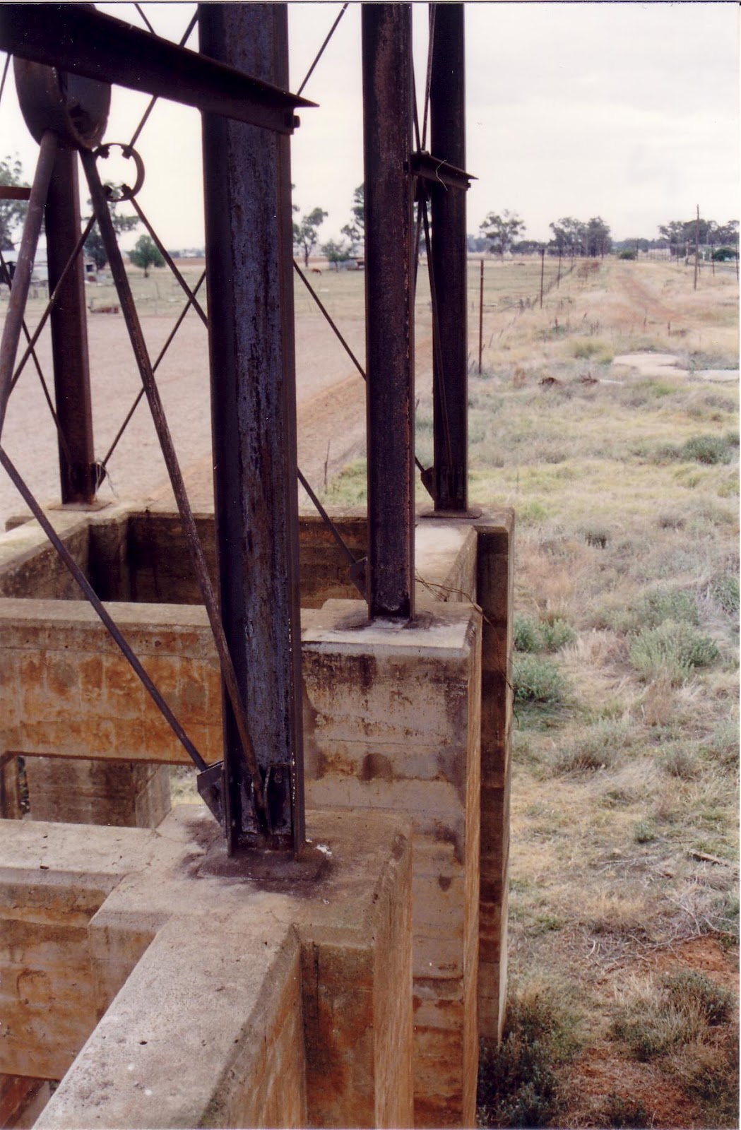
The foot of the steel columns showing the newer type of attachment to the foundations – this example at Binnaway.

Friday, 30 March 2012

NSW Water Facilities Part 4 - 1916 to 1932

This period can be described as the third period of expansion. By 1915 the North Coast line was well on the way to completion and around half of the country branchlines had been completed. The majority of lines built in this period were expected to have a lower return than the lines built in the previous 20 years, so much so that some of the lines closed before the end of steam.
This was also the period where precast concrete was used in the construction of buildings and other infrastructure.
Pre cast concrete was first used in the construction of the station building at Lake Cargelligo which was opened for traffic on 13th November 1917. This was evidently a trail as the for the next 2 years the lines that were opened did not use this material in their construction. It was not until the opening of the Kempsey to Macksville section of the North Coast line on 1 July 1919 that the material was used again. This time every branchline built through to 1932 used the material.
The construction of the water tanks went through a change at the same time and the panels used in to tank began to be constructed by the PerWay Workshops in Newcastle. The standard set of plans were also reissued at the time.
The catalyst for all of this change was the responsibility for new lines reverting back to the railways after 23 years with the Public Works Department. While new designs (the precast buildings in particular) were issued the over-riding reason for these were (cost and time). The new designs and materials enabled large batches of part to be created for various locations without reference to the actual site.
Wile the structures were similar to those previously built there were four distinct changes or new designs that occurred during this period:

  • Large Concrete Bases
  • New Design of Timber Stands
  • American Type Jibs
  • Tank Panels made by Per Way Workshops

The Concrete Bases

In 1917 the railways performed an experiment with the method of construction of the stand. Instead of the normal style of concrete footings a foot or so high large four legged arch structures were used. Formwork was built, the steel columns placed and the concrete poured. The result was an extremely stable stand.
Three of the type were constructed over a short period in 1917 at Ungarie and Lake Cargelligo on the Wyalong to Lake Cargelligo section and Wirrinya (construction name Coolana) on the Caragabal to Forbes section. All three structures were built as single tier 20000 gallon tanks with Lake Cargelligo being provided with a jib. Wirrinya gained an additional tier, making its capacity 40000 gallons in August 1926.
The arch concrete structures were in total 13’ high and approximately 11’ wide. The example at Lake Cargelligo being slightly different than the other two examples in that the piers extended a further 4” above the arch although it seems as they addition was added some time after the initial construction. Above the concrete structure the stand was similar to those that were constructed previously.
The railways only built three of these types of stand. It was no doubt an experiment that was quickly found to be not suitable primarily due to the time taken to construct the stand. While all three tanks were built in open and possibly wind blown areas there are many tanks built after these there that are in similar open areas that did not have this type of stand.

Lake Cargelligo, 21 August 1998


Lake Cargelligo, 21 August 1998
Wirrinya, 29 July 1993

New Timber Stand Design

In late 1918 there was a shift away from stands made of steel and a return to those made of timber. The new stand while similar to previous timber stands but was the diagonal bracing was external of the timber piers rather than inside the piers.
The foundations of the stand were 2’6 square concrete with a 1 ¾” diameter and 1’9” long steel rod embedded in the centre of each foundation. 12” square timber piers were centred on the steel rod with 26’ long 12” square bearer resting on the piers. 12” by 6” joists resting on the bearers and supported the tank. In the case of the 20000 and 40000 gallon tank there were 16 piers, 4 bearers and 7 joists. The piers were braced in sets of four with 6” x 3” diagonal braces between the piers. Where the bracing crossed a 1” diameter galvanised pipe was used to tie them together. The stand was held together by 7/8” diameter bolts of various lengths. Strap bolts were used to connect the piers and the bearers.
The new stand was first used in late 1918 at Euabalong West on the Condobolin to Trida. This was followed by the following tanks:
  • Warrell Creek Tank (Eungai – Macksville)
  • Broken Hill
  • Coolah
  • Tumbarumba
  • Bombala
  • Tallimba
  • Rankins Springs
  • Hillston
  • Yearinan
  • Batlow
  • Baradine
  • Yannagee
  • Megan
  • Mole Creek Tank
  • Dorrigo
  • Westby
The tank at Rankins Springs showing the general arrangement of the structure
 All the tanks were of 20000 gallons capacity except Yannagee (40000 gallons), Megan (10000 gallons) and Dorrigo (10000 gallons). The majority also had attached swinging jibs with only Broken Hill and Yannagee being the exceptions.
Then as suddenly as they started using this type of stand they returned to a steel stand and remained with the steel stand for the remainder of the tanks constructed.
Today only five of this type of structure remain – Tallimba and Rankins Springs (both on the Rankins Springs line), Yannagee (moved to Cooma in late 2001), Tumbarumba (jib removed) and Mole Creek Tank on the Dorrigo line. The structure at Megan, also on the Dorrigo Line is partially (mostly) dismantled. The foundations can still be found at Westby, Coolah and Yearinan


Detail of the structure at Rankins Springs showing the bracing ties. 21 August 1998
Detail of the method of attaching the bearers to the joist on the Rankins Springs tank. 21 August 1998
The strap bolts that secure the bearers to the piers on the Rankins Springs tank. 21 August 1998
The tank at Rankins Springs showing the attached jib. 21 August 1998

Lifting (American) Jibs

During the construction of the Batlow line in 1922-23 (it was opened on 17th December 1923) a new type of jib was used. The lifting jib was a copy of a type widely used in the United States for many years (hence their name) and it’s the origin of its use in New South Wales is not known. IT is suggested that it may be as a result of a visit by senior railway staff to the Americas and Europe in the early 1920’s or possibly seeing its use in Europe during the First World War – a large number of water column in Europe using this type.
Where as previous jib designs swung out from the tank the lifting jib simply lifted clear of the loading gauge with the train passing under it. The jib was made from No. 6 SWG Galvanised Iron and was thus significantly lighter than the swinging type. The support and lifting mechanism of the jib being more complicated though.
Two more lifting jibs were built in 1924 on the Dorrigo line and there was then a four year gap before the next example was constructed – during this four year period very few elevated tanks were constructed and this is the main reason for there being gap. Five more examples were constructed from late 1928 through to 1932 and with most tanks located in the country being provided with a lifting jib.
Lifting jibs were provided on the following tanks – the approximate construction date is also listed:
  • Batlow (12.1923)
  • Megan (11.1924)
  • Dorrigo (11.1924)
  • Bullenbung Creek (10.1928)
  • Naradhan (1.1929)
  • Casino (6.1930)
  • Crooble (6.1932)
  • Boggabilla (6.1932)
  • Taralga (removed from Dubbo)
There were two tanks constructed during this period where the type of jib (swinging or lifting) has not been able to be established. They are at Westby (constructed in 1925) and Ballina (constructed in 1930).


The lifting jib at Naradhan showing the general arrangement of attachment to tank with a steel stand  21 August 1998
The spout, which  was located on the end of the jib has fallen off from the jib at Naradhan. 21 August 1998


New Panels and other Minor Changes


The panels that made up the tanks also underwent a change during this period. In 1917 following the passing of the Government Railways (Amendment) Act the previous year and as a result the passing of the responsibility of the new lines from the Public Works back to the Railways there was a move to bring the construction of components in-house.
The design of the panels remained the same although the scalloping on the outside changed slightly. The major change to the panels was that the casting became the responsibility of the PerWay Workshops in Newcastle. Each year the workshops would cast a number of panels and some of them would have a builders plate cast into the outside of the panels. This was the first time since the round tanks that there was an indication on the tank of who built them. A 20000 gallon tank required 60 square panels, 32 corner panels and 4 corner segments, the segments being the small sections at the bottom corners of the tank. 40000 gallon tanks required another total of 84 square panels. It is estimated that the workshops cast a minimum of 800 panels per year between 1917 and 1929.

The builders plate on a panel of the tank at Naradhan 21 August 1998
The interior of the tank at Naradhan showing the interior webbing of each plate and the bracing style used on a single tier tank of the period. 21 August 1998.
The interior of the tank at Naradhan showing a section where two panels join. Iron filings were used to seal the two panels together to avoid leakage. 21 August 1998
 There was another minor change in the construction method of the tanks as the style of bracing changed from using a flat bar to a section of angle. This was no doubt due to the increased rigidity provided by the angle over the flat bar. It is interesting to note that today, some 40 years after some tanks were regularly filled with water, a large number of the flat bars have at worst rusted away or at best in a state where they do not provide any real support. The angles on the other hand do not show this level of deterioration.